


|
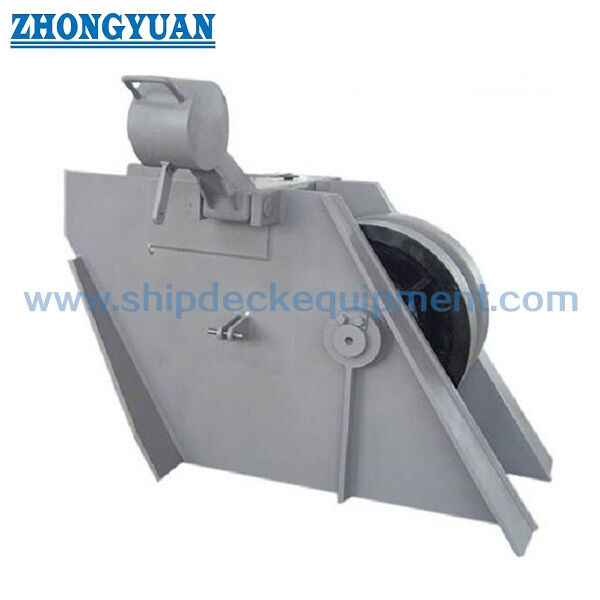
Włókno typu kotwicy blokada łańcucha dla 42 ′′ 132 mm łańcucha. CB / T 3844-2000
Szczegóły Produktu:
| Miejsce pochodzenia: | Chiny |
| Nazwa handlowa: | Zhongyuan Marine Equipmen |
| Orzecznictwo: | CCS, NK, BV, ABS, DNV, LR, KR, IRS, RS, RINA, CRS, Makers Test Certificate |
| Numer modelu: | Standardowy lub dostosowany |
Zapłata:
| Minimalne zamówienie: | 1 jednostka |
|---|---|
| Cena: | Based on quotation |
| Szczegóły pakowania: | Eksportuj standardową paletę lub niestandardowe opakowanie |
| Czas dostawy: | Na podstawie wymagań projektu |
| Zasady płatności: | T/T, akredytywa |
| Możliwość Supply: | Produkcja zindywidualizowana w oparciu o wymagania projektu |
|
Szczegóły informacji |
|||
| Standard techniczny: | GB/T 3844-2000 | Typ: | Typ dźwigni rolkowej |
|---|---|---|---|
| Rozmiar łańcucha: | 42-132 mm | Przybory: | Stal miękka, stal C-Mn, stal nierdzewna, stal odlewnicza, żeliwo sferoidalne, kucie stali |
| Certyfikaty klasyfikacyjne: | CCS, NK, BV, ABS, DNV, LR, KR, IRS, RS, RINA | Obróbka powierzchniowa: | Sandblasting do S2.5 + jedna warstwa podkładu sklepu epoksydowego, ocynkowane, wypolerowane, sperson |
| Podkreślić: | ogranicznik łańcucha dźwigni rolki,ogranicznik łańcucha dźwigni rolki morskiej,GB / T 3844-2000 Sprzęt do cumowania statków |
||
opis produktu
Zacisk łańcucha kotwicznego typu rolkowego do łańcucha 42–132 mm | CB/T 3844-2000
Przegląd produktu
Zacisk łańcucha kotwicznego typu rolkowego CB/T 3844-2000 to urządzenie do mocowania łańcucha zainstalowane na pokładzie, stosowane w układach kotwiczenia statków do zabezpieczania łańcucha kotwicznego i przenoszenia sił łańcucha na konstrukcję statku, jednocześnie zmniejszając statyczne obciążenie utrzymujące przenoszone przez kabestan. Jest on zazwyczaj instalowany w linii łańcucha kotwicznego między kabestanem kotwicznym a kluchem.
Niniejsza strona obejmuje rozmiary nominalne 44–132 dla łańcuchów kotwicznych klasy 1, klasy 2 i klasy 3 o średnicy 42–132 mm zgodnie z normą CB/T 3844-2000. W wersji z 2000 roku zastosowano spawane korpusy z blachy stalowej rozciągnięte do pokładu w celu bezpośredniego spawania oraz wzmocniono płyty boczne w obszarze nacisku ostrza zacisku. Ostateczną wysokość zacisku łańcucha, kąt wejścia/wyjścia łańcucha i wyrównanie linii łańcucha należy sprawdzić w odniesieniu do układu statku i zatwierdzonego rysunku instalacyjnego.
Szybkie specyfikacje
• Typ produktu: zacisk łańcucha kotwicznego typu rolkowego → zabezpiecza łańcuch kotwiczny w linii kotwiczenia i zmniejsza obciążenie utrzymujące przenoszone przez kabestan.
• Norma techniczna: CB/T 3844-2000 → aktualna chińska norma branży morskiej dla zacisków łańcuchowych typu rolkowego; dotyczy łańcuchów kotwicznych klasy 1, 2 i 3 o średnicy od 42 do 132 mm.
• Zakres średnic łańcucha: 42–132 mm poprzez rozmiary nominalne 44–132 → wybierz rozmiar nominalny na podstawie rzeczywistej średnicy łańcucha kotwicznego i rysunku statku.
• Weryfikacja obciążenia: CB/T 3844-2000 zawiera wytyczne dotyczące kontroli wytrzymałości i określone obciążenia testowe → każde stwierdzenie o 80% minimalnego obciążenia zrywającego łańcucha należy traktować jako podstawę projektową / weryfikacyjną, a nie jako dopuszczalne obciążenie robocze (SWL) produktu.
• Ostrze zacisku i wałek rolki: norma określa wymagania dotyczące materiału komponentów i wymaga normalizacji wałka rolki i ostrza zacisku przed obróbką mechaniczną → ostateczną klasę materiału i wszelkie zamiany projektowe należy potwierdzić.
• Wzmocnione płyty boczne: wersja z 2000 roku wzmacnia boczne płyty korpusu w obszarze nacisku ostrza zacisku → poprawia lokalne przenoszenie obciążenia na spawany korpus i konstrukcję pokładu.
• Rolka i smarowanie: części obrotowe są smarowane, a zmontowana rolka musi obracać się swobodnie z dokładnym pozycjonowaniem → wspiera ruch łańcucha i konserwację.
• Ochrona powierzchni: oryginalna norma określa jedną warstwę podkładu antykorozyjnego, a następnie powłokę bitumiczną, ze smarem na częściach obrotowych → epoksyd, galwanizacja lub inne nowoczesne systemy powłok są alternatywami specyficznymi dla projektu.
Główne parametry techniczne
|
Średnica nominalna (mm) |
Średnica łańcucha (mm) |
L |
B |
D |
h1 / h2 |
Waga (kg) |
|---|---|---|---|---|---|---|
| 44 | 42~44 | 1000 | 380 | 484 | 392 / 281 | 274 |
| 48 | 46~48 | 1050 | 446 | 528 | 414 / 306 | 351 |
| 52 | 50~52 | 1100 | 510 | 572 | 440 / 338 | 451 |
| 56 | 54~56 | 1150 | 556 | 600 | 460 / 354 | 536 |
| 60 | 58~60 | 1200 | 610 | 620 | 490 / 378 | 651 |
| 64 | 62~64 | 1250 | 666 | 640 | 520 / 400 | 753 |
| 68 | 66~68 | 1300 | 732 | 680 | 540 / 420 | 939 |
| 73 | 70~73 | 1350 | 800 | 730 | 580 / 460 | 1178 |
| 78 | 76~78 | 1400 | 865 | 780 | 630 / 490 | 1422 |
| 84 | 81~84 | 1460 | 940 | 840 | 670 / 530 | 1758 |
| 90 | 87~90 | 1540 | 1030 | 900 | 720 / 570 | 2171 |
| 95 | 92~95 | 1600 | 1080 | 950 | 760 / 610 | 2567 |
| 102 | 97~102 | 1680 | 1150 | 1020 | 800 / 650 | 2755 |
| 107 | 105~107 | 1750 | 1210 | 1070 | 860 / 690 | 3640 |
| 114 | 111~114 | 1820 | 1270 | 1140 | 910 / 740 | 4302 |
| 122 | 117~122 | 1880 | 1340 | 1220 | 980 / 790 | 5326 |
| 132 | 124~132 | 1960 | 1440 | 1320 | 1060 / 860 | 6244 |
Przewodnik wyboru i zapytania
Krok 1: Potwierdź zacisk łańcucha kotwicznego typu rolkowego CB/T 3844-2000 i rozmiar nominalny 44–132 zgodnie z rzeczywistą średnicą łańcucha kotwicznego.
Krok 2: Podaj pozycję instalacji na statku, układ kabestanu do kluchem, kąt wejścia łańcucha i kąt wyjścia łańcucha, aby można było sprawdzić wysokość linii łańcucha i wyrównanie.
Krok 3: Potwierdź klasę łańcucha kotwicznego, minimalne obciążenie zrywające, wymaganą podstawę projektową / testową obciążenia i wymagania klasyfikacyjne. Nie konwertuj oświadczenia o 80% MBL na SWL produktu.
Krok 4: Potwierdź materiały komponentów i wszelkie zatwierdzone nowoczesne odpowiedniki spawanych korpusów, wzmocnionych płyt bocznych, ostrza zacisku, rolki, wałka rolki, tulei, sworzni i powiązanych części.
Krok 5: Potwierdź system ochrony powierzchni, wymagania dotyczące smarowania, zakres inspekcji / NDE, wymagania dotyczące certyfikatu producenta lub klasy, ilość, miejsce dostawy i wymagany czas dostawy.
Krok 6: Dostarcz rysunek GA, rysunek instalacyjny, zdjęcia referencyjne lub informacje o próbce zamiennej, gdy zacisk łańcucha jest przeznaczony do projektu naprawy lub modernizacji.
Struktura
Spawany korpus z blachy stalowej montowany na pokładzie | Rolka | Wałek rolki | Ostrze / dźwignia zacisku | Wzmocnione płyty boczne w obszarze nacisku ostrza | Tuleje / sworznie | Bezpośrednia podstawa spawana do pokładu | Smarowane części obrotowe
Zalety mocowania łańcucha kotwicznego, produkcji i inżynierii
• Bezpośredni spawany do pokładu korpus → wersja z 2000 roku rozciąga korpus z blachy stalowej do pokładu, upraszczając standardowy interfejs instalacyjny w porównaniu z wcześniejszym układem.
• Wzmocniony obszar nacisku ostrza → lokalne wzmocnienie płyty bocznej jest skoncentrowane tam, gdzie ostrze zacisku przenosi siłę łańcucha na korpus.
• Kontrolowane działanie rolki → zmontowana rolka powinna obracać się swobodnie i być dokładnie pozycjonowana; części obrotowe są smarowane smarem.
• Kontrola obróbki cieplnej → norma wymaga normalizacji wałka rolki i ostrza zacisku przed obróbką mechaniczną; wszelkie alternatywne materiały / procesy obróbki cieplnej powinny zostać zatwierdzone.
• Geometria instalacji ma znaczenie → wysokość zacisku łańcucha oraz kąty wejścia / wyjścia łańcucha powinny prawidłowo wyrównywać łańcuch z rolką i ostrzem zacisku oraz unikać niezamierzonego obciążenia bocznego.
• Standardowy test obciążenia → zacisk jest poddawany określonemu obciążeniu testowemu przez 5 minut, po czym główne komponenty nie powinny wykazywać pęknięć ani deformacji; to obciążenie testowe nie jest tym samym terminem co SWL.
• Podstawa inspekcji → stan wizualny, jakość spawania, weryfikacja właściwości materiałowych i działanie rolki są standardowymi kontrolami; dodatkowe NDE i nadzór klasyfikacyjny są zgodne z wymaganiami projektu.
Niestandardowe atrybuty
• Norma: CB/T 3844-2000 → aktualna norma dla zacisków łańcuchowych typu rolkowego dla łańcuchów kotwicznych klasy 1 / 2 / 3 o średnicy 42–132 mm.
• Typ: Zacisk łańcucha kotwicznego typu rolkowego / rolkowo-dźwigniowego → urządzenie do mocowania łańcucha instalowane na pokładzie dla systemów kotwiczenia statków.
• Rozmiar nominalny: 44–132 → wybierz na podstawie rzeczywistej średnicy łańcucha kotwicznego pokazanej w tabeli normy.
• Rozmiar łańcucha: 42–132 mm, klasa 1 / 2 / 3 → inne rozmiary wymagają innego zatwierdzonego projektu lub normy.
• Podstawa obciążenia: kontrola wytrzymałości CB/T + określone obciążenie testowe → odniesienie 80% MBL łańcucha nie może być publikowane jako SWL produktu.
• Ostrze zacisku / wałek rolki: materiał i obróbka cieplna specyficzna dla komponentu → oba są normalizowane przed obróbką mechaniczną.
• Wzmocnienie płyty bocznej: skoncentrowane w obszarze nacisku ostrza zacisku → wspiera lokalne przenoszenie obciążenia na korpus.
• Dane instalacyjne: wymagany kąt wejścia / wyjścia łańcucha i pozycja instalacji → potwierdź wysokość zacisku i geometrię linii łańcucha.
• Podstawa materiałowa: spawany korpus z blachy stalowej z materiałami specyficznymi dla komponentów → nowoczesne odpowiedniki wymagają zatwierdzenia projektu.
• Ochrona powierzchni: standardowy podkład + powłoka bitumiczna ze smarowanymi częściami obrotowymi → nowoczesne powłoki są specyficzne dla projektu.
• Certyfikacja: zgodnie z wymaganiami projektu → certyfikaty producenta / materiałowe i obecność klasy zależą od zakresu zamówienia.
Jak to działa
Łańcuch kotwiczny wchodzi do zacisku → Rolka prowadzi linię łańcucha → Ostrze / dźwignia zacisku blokuje łańcuch → Wzmocniony korpus przenosi obciążenie na pokład → Obciążenie utrzymujące kabestanu jest zmniejszone
Zastosowania
Układ kotwiczenia statku | Obszar pokładu kabestanu kotwicznego | Zacisk łańcucha między kabestanem a kluchem | Wyposażenie pokładu dziobowego | Statki towarowe | Tankowce | Masowce | Kontenerowce | Barki robocze | Projekty budowy nowych statków i wymiany w naprawach
Certyfikaty i zalety
Certyfikaty mogą być organizowane zgodnie z wymaganiami projektu, zakresem inspekcji, identyfikowalnością materiałów i procedurą zatwierdzania towarzystwa klasyfikacyjnego.
Certyfikacja: CCS, NK, BV, ABS, DNV, LR, KR, IRS, RS, RINA, CRS, Certyfikat testu producenta.
Rysunki i zdjęcia

FAQ
P1: Jakie informacje są potrzebne do potwierdzenia wysokości zacisku łańcucha?
O1: Podaj pozycję instalacji, kąty wejścia / wyjścia łańcucha, relację kabestanu do kluchem, fundament pokładu i rzeczywistą średnicę łańcucha, aby można było sprawdzić wysokość linii łańcucha i zazębienie ostrza zacisku.
P2: Czy 80% minimalnego obciążenia zrywającego łańcucha kotwicznego to SWL produktu?
O2: Nie. CB/T 3844-2000 wykorzystuje wytyczne dotyczące kontroli wytrzymałości i określone obciążenia testowe. Oświadczenie o 80% MBL jest odniesieniem projektowym / weryfikacyjnym, a nie SWL produktu; ostateczna terminologia jest zgodna z zatwierdzoną podstawą projektową.
P3: Jakie standardowe punkty jakości i inspekcji należy sprawdzić?
O3: Sprawdź stan powierzchni i spawów, zgodność materiałową, swobodne / dokładne działanie rolki oraz określony 5-minutowy test obciążenia. Po teście główne komponenty nie powinny wykazywać pęknięć ani deformacji.